Tackling timber frame terminology

Getting to know the terminology of timber frame construction is a big step in every self-builder’s journey. Learning the ‘lingo’ can aid and ultimately lead to stronger communication channels with your project team. This, in turn, can result in better decision-making. Sound communication and greater levels of knowledge are two consistent elements of all successful self-build projects which is why we have created this post.
This article highlights some of the key terminologies you are likely to encounter and is designed to help you overcome the hurdle of jargon. As they say, knowledge is king, and a picture paints a thousand words. We hope this information supplements your existing self-build knowledge so that you can start building successful communication channels with your team.
Please note that this article details typical timber frame terminology, materials, and details. The use of these products and the detail in which they are applied can vary from project to project. The specification of structural members and the overall structural design of a timber frame dwelling must be instructed by a certified structural engineer.
This information is provided for informational purposes only and the application of the products mentioned are governed by the current building regulations.
Further details, information, and advice are available from our technical team. Contact us here.
External Walls

CAVITY BARRIERS – are positioned at specific locations within the external cavity to resist the spread of fire. They are located within the external cavity at corners, junctions, mid-floor levels, gable lines, eaves level, around windows and doors, and vertically at specific intervals. There are a variety of products that can be used as cavity barriers and installation details can change depending on your specific design. There are likely to be over 150m of cavity barriers within a typical-sized timber frame dwelling.
EXTERNAL JOINERY – is a term most commonly used to describe windows and external door products.
COMPRIBAND – is a flexible, expanding sealant tape that is fitted around external joinery products. The compriband tape is a critical waterproofing element. It aids thermal performance and allows the external joinery product to breathe as designed.
PINCH BATTEN – also known as a ‘firestop’ batten when positioned around external joinery. Formerly, the primary function of a pinch batten was 60 minutes of fire resistance (as it acts as a cavity closer) and for the actual fixing of the window. Today, most windows are set with fixing brackets, therefore the pinch battens simply wedge the expanding compriband tape between the window frame and batten. Simply put, it provides a stop for the compriband to neatly expand to.
BREATHER MEMBRANE – all timber frame products will have an external breather membrane. This membrane is moisture resistant yet breathable. This means it keeps moisture away from the timber frame structure yet allows the structure to breathe. This silver reflective product also positively contributes to the thermal performance of the external wall element.
EXTERNAL CAVITY – all timber frame dwellings will have a ventilated cavity of some sort. In the external wall image above the external leaf is masonry blockwork with a standard 50mm cavity between masonry leaf and timber frame structure. The cavity plays a number of critical roles in the performance of a timber frame dwelling, most of which centre around the control of moisture. Remember that the cavity is ventilated, therefore there is always movement of air within. Any moisture that does penetrate the external leaf will not bridge to the timber frame structure due to the cavity gap and any moisture that may somehow exist would either drain vertically or evaporate due to ventilation.
EXTERNAL CILL – in most window products there will be an external extension cill. The primary purpose of the external cill is to take moisture away from the timber frame and window product, so it is a critical element in the waterproofing detail of a timber frame dwelling.
FRAME TIE – ties the masonry leaf to the timber frame structure. The masonry leaf in a timber frame dwelling is essentially a stand-alone structure. It carries its own weight and not much more. Frame ties are set at multiple locations within the mortar course of the masonry leaf and fixed to the timber frame studs, meaning that the external leaf is supported laterally by the timber frame structure. In a standard size timber frame house, there is likely to be over 1000 frame ties set within the external masonry leaf.
EXTERNAL LEAF – every timber frame dwelling has an external leaf. It could be masonry block (ready for render as shown in this image), traditional brick, render board and render, timber-clad or other. Other than completing the final external aesthetic of a home, the external leaf plays an important role in the weatherproofing of a timber frame home. In fact, the masonry leaf on a timber frame home could be best described as a glorified weather shield. There is very little structural significance to this leaf. More importantly, it plays a vital role in keeping a timber frame dwelling dry over the lifetime of the dwelling.
Roof Structures
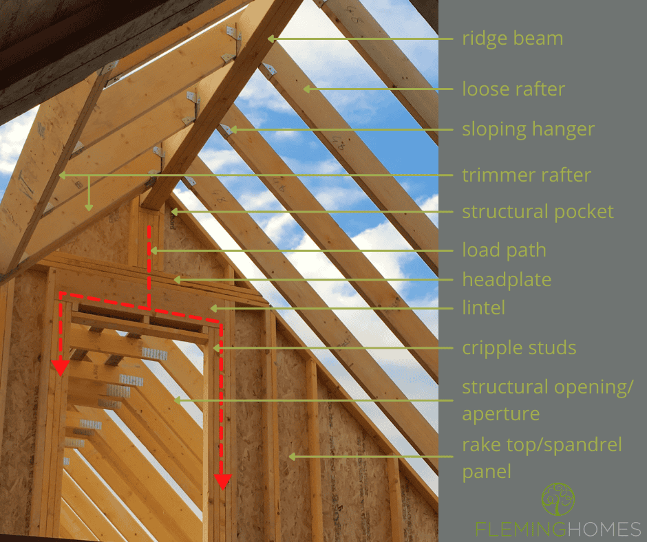
RIDGE BEAM – are featured in most roof structures in some shape or form. In this example, a timber ridge beam is used to support loose rafters that create a vaulted ceiling structure. The type of material used for a ridge beam depends on the span of the beam and loads applied to it. Under greater loads, an engineered timber roof bridle may be used, like kerto or glulam. Steel roof bridles are very common nowadays, such is the popularity of large, vaulted ceiling areas.
LOOSE RAFTER – are also featured in most roof structures in some shape or form. In combination with ridge beams (or other structural members), loose rafters create the sloping section of a vaulted ceiling. In the example shown in the image above, a solid 195 x 45mm timber rafter set at 600mm centres is utilised. The type of material and the setting out spacings (often termed “centres”) depend on the span of the rafter and the loads applied to it. Under greater loads, an engineered rafter may be used, like kerto, glulam, “I” joist or a posi rafter. Likewise, the depth of a solid timber rafter could be increased, and the spacings/centres narrowed. Many design factors will influence this decision. In most scenarios, the primary layer of roof insulation will be housed between the structural roof rafters.
SLOPING HANGER – this prefabricated metal hanger forms the structural fixing between the loose rafter and the ridge beam. Rafter hangers come in a variety of shapes and sizes, depending on the structural fixing required. The type of hanger specified will depend on both the vertical and lateral loads that are applied to the connection.
TRIMMER RAFTER – ‘trimmers’ are used to form openings within a roof structure. Trimmer rafters ‘frame out’ an area greater than the module spacings of the roof rafters (or truss). Think of a simple 2D box with another box inside. The outside box is strong and rigid so that the inside box doesn’t need to be as strong or rigid. The outside box is the trimmer rafters and the inside box a rooflight or dormer window (for example). The trimmer rafters take the greater structural loads so that the element within the trimmers do not have to.
STRUCTURAL POCKET – are very common in timber frame construction. Simply, a pocket is formed within the timber frame structure to house a structural beam (or other structural member).
LOAD PATH – being able to identify (or at least understand) load paths in a timber frame dwelling is one of the most underrated abilities a self-builder can possess. In this example the load path is simple; the load of the ridge beam is applied to the studs directly beneath, which then travels to the lintel over the structural opening, dispersed through the lintel and down the cripple studs either side of the opening. Simple right? OK, so maybe a detail as fine as this is a step too far, however, zoom out and consider the continuation of this path and you may start to see the point. Starting at the ridge beam the load must travel through the building right to the foundations. This means that there needs to be ‘something’ below this image to receive it. Most commonly the load path would be collected by a load-bearing wall, but it is not always so. In this case, structural beams or other structural members will need to be introduced which can have a significant impact on budget. Every designer should consider load paths when designing, but you will be surprised how many do not. Your knowledge and understanding of load paths could help you design a more practical and cost-efficient structure!
HEADPLATE – as the name implies, a headplate is set over the head of a load-bearing wall panel. A headplate helps form the lateral fixing between prefabricated panels and helps disperse vertical loads applied to a panel through the structural studs.
LINTEL – a lintel provides the structure to bridge over an opening, such as a door or window.
CRIPPLE STUDS – a “stud” is a vertical timber set within a timber frame panel. A common timber frame panel will have a single timber stud set at 600mm intervals (centres). A bank of studs set under a lintel, beam or similar are referred to as cripple studs. Cripple studs receive the loads that are applied to the lintel and continues its path vertically through the structure. Cripple studs can be singular or grouped in multiples depending on the loads applied.
STRUCTURAL OPENING / APERTURE – a structural opening or aperture describes any structural opening within a dwelling, for example, an internal door, an external door, or a window.
RAKE TOP / SPANDREL PANEL – there are several names given to a sloping panel; rake top, spandrel, peak, sloping, apex are all words commonly used to describe a prefabricated panel that is triangular and/or has an angled head.
Attic Truss Scenario
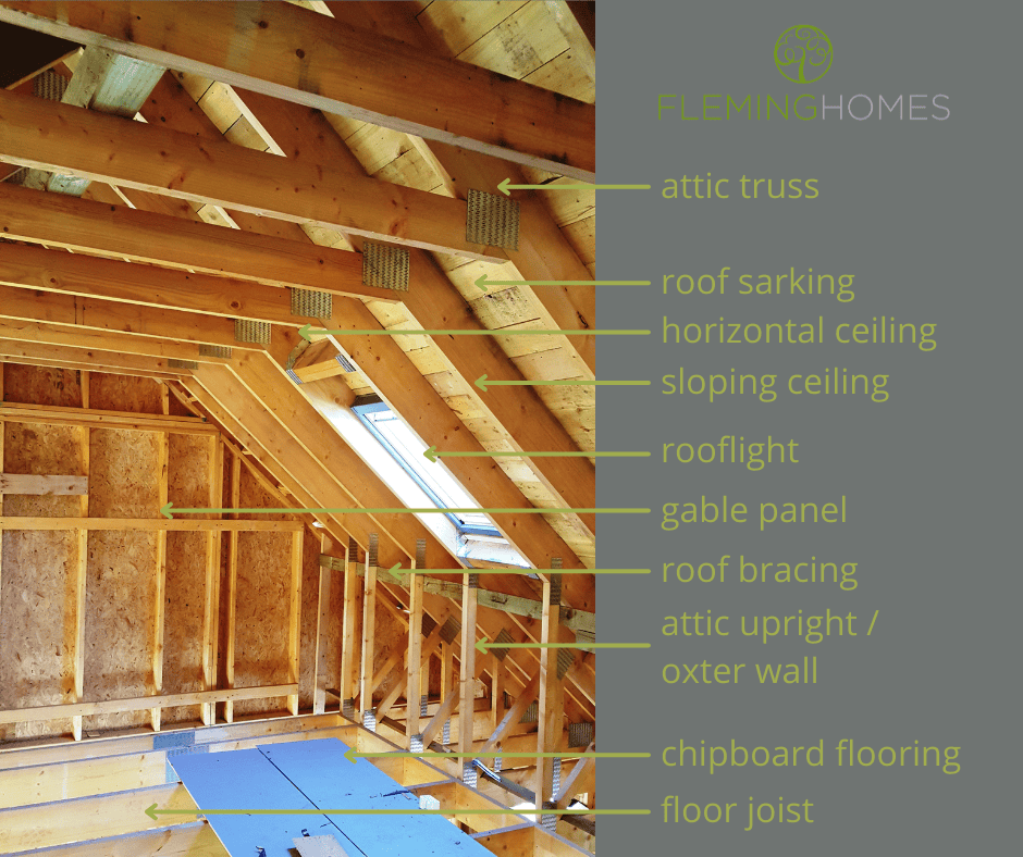
ATTIC TRUSS – a truss is a prefabricated roof element that forms the shape and structure of a roof. There are many kinds of roof trusses, such as fink, mono, raised tie, boxed, scissor, attic, all of which perform a different function within a roof structure. An attic truss is a type of truss that forms both the roof and floor structure in one single truss element, creating a habitable or “attic” space within. They are typically used in ‘room in the roof’ dwellings or dwellings that incorporate an attic space. They can aid cost efficiency of a timber frame structure because they are prefabricated and form the roof and floor in one application.
ROOF SARKING – is a structural cladding fixed over the structural roof members for structural rigidity and additional weather proofing. There are many ways to “sark” a house. In the image above, you can see the underside of 150 x 22mm softwood timber boards fixed perpendicular to the structural roof members. Other options include sheets of OSB or plywood. Such material types would all be referred to as roof sarking in a conversation about your roof structure. The decision on which type of sarking to use is usually determined by the finished roof cladding (providing the sarking type is not a prerequisite for your structural design). Slate roofs tend to have softwood sarking as it forms a solid structure for fixings. Tiled roofs tend to have OSB sheet sarking with counter and tile battens for fixing. All forms of sarking must consider the breathability of the roof space and all forms perform differently in terms of ventilation flow. Softwood sarked roofs are designed to breathe through the entire roof scape. Each board has a gap between and the structure ventilates through a breathable roof membrane. OSB sarked roofs are designed to ventilate at specific locations. Continuous ridge and eaves ventilation details are applied along with a non-breathable roof membrane in sheet sarked roofs. ‘Sarking’ is a common word in Scotland but can be very foreign in England and Wales. That’s because in Scotland it’s mandatory to have structural sarking whereas in England and Wales it’s not. In our opinion, a sarked roof is a better roof.
HORIZONTAL CEILING /SLOPING CEILING – it is good to know the different ceiling types in a dwelling. As you may have guessed, a horizontal ceiling describes the flat horizontal ceilings and sloping ceiling describes ceilings on an angle or slope. It sounds simple but add other areas of a dwelling like floors, external walls, internal walls, all of which require performance vs budget considerations when analysing a timber frame quotation and it starts to get a little tricky. Knowing the common reference and how they are typically detailed will help. The big difference to identify between horizontal and sloping ceilings is how they are insulated. Most horizontal ceilings will be filled with layers of glassfibre insulation, whereas sloping ceilings are commonly insulated with rigid insulation products. This is primarily due to the ‘space’ available in both areas influencing insulating material options. Horizontal ceilings have space (from ceiling to ridge), so it is economical to add layers of cheaper insulating products to obtain a certain level of performance. Sloping ceilings have less space (primarily determined by the depth of the rafter) meaning there are less options to achieve the same level of performance. Therefore, different products and details are used, with different performance levels and budget implications. All of which are decisions informed by understanding the difference between horizontal and sloping ceiling areas.
ROOFLIGHT – is a window set within the roof structure. There are many different styles of rooflights; domes, lanterns, skylights, tinting rooflights, remotely operated rooflights, windows that open into balcony rooflights, and so on. There are also many different suppliers of rooflights although one is privileged enough to have their name monopolise the description of most rooflights in the UK. The rooflight shown in the image above is often simply referred to as a Velux window.
GABLE PANEL – a gable in a dwelling is the vertical wall beneath the sloping pitch of a roof, typically at the “ends” of a roof structure. The gable panel is the timber frame structure that creates the gable wall. A gable panel is constructed in the same way as a regular external wall panel, although it has a sloping top rail. One of the big benefits of timber frame construction is that the structure can be prefabricated. Computer-aided designs and factory-controlled manufacturing means that angled gable panels can be erected on-site within minutes, just as a regular wall panel.
ROOF BRACING – in addition to roof sarking (if applicable), roof bracing contributes to the structural rigidity of a roof structure. Roof bracing materials run perpendicular to the roof structural members, in the case of the image above, the attic trusses. They essentially tie multiple trusses together so they are braced for strength. The amount of bracing required for a roof structure will be determined by a number of factors, including the roof type and the lateral loads (which is a fancy word for wind). Typically, roofs without sarking will have more bracing than roofs with. Therefore, in English and Welsh projects it is very common to see far more lengths of roof bracing within a roof than you would see in a Scottish roof.
ATTIC UPRIGHT / OXTER WALL – is the part of an attic truss that forms the stub internal wall. “Oxter” is a Scottish term for an armpit, so with a little imagination you may see the reference. The size of an attic upright / oxter wall in an attic truss is usually around 1.2m high. As it is formed as a part of the attic truss, the wall structure is in-situ as soon as the truss is erected.
CHIPBOARD FLOORING – is a very common structural floor material which is typically laid directly over the structural floor. Made up of recycled composite material, a chipboard sheet will have a tongue and groove connection which helps multiple sheets adjoin to create a structurally rigid floor. Chipboard is typically ‘glued not screwed’, which is a detail established by product designers to limit the potential for squeaky floors. One reason for a squeaky floor can be movement of floor joists transposing to movement of the chipboard, which can then cause friction at a fixing point such as a nail or screw. In simple terms, the chipboard moves up and down (as the floor joists moves up and down under loads), the nail stays stationery, and the difference equals noise. The difference causes friction, and a squeak occurs as the nail rubs against the chipboard floor, hence the floor is glued. By removing the fixing, you remove one potential element which may lead to the dreaded squeaky floorboard.
FLOOR JOIST – a floor joist is the structural member that creates the structural floor of a dwelling. In this example the floor joist is a part of the prefabricated attic truss. In this application the floor joist would be better described as the ‘bottom chord’ of the attic truss, however it performs the same function as a loose floor joist. There are several different kinds of joist materials that can be utilised. Solid timber is very common, as shown in the image above, in this bottom chord application. Engineered joists such as I joists or posi joists are very popular for their ability to reduce deflection (movement) and achieve greater spans. They are also easier to run services within which is a contributing factor to their popularity today. (For more information see the section on posi joists below).
Ground Floor

LINTEL – a lintel provides the structure to bridge over an opening, such as a door or window. The image above shows a lintel set over a door opening within an internal wall. Whether an opening requires a lintel depends on whether the wall is loadbearing. If there are no significant loads to carry, like in a non-loadbearing wall, there will be no lintel.
HEADPLATE – as the name implies, a headplate is set over the head of a load-bearing wall panel. A headplate helps form the lateral fixing between prefabricated panels and helps disperse vertical loads applied to a panel through the structural studs.
INTERNAL WALLS – also referred to as partitions, internal walls divide space in a dwelling to create rooms. They also play an important role in the overall structure of a building. There are three main classes of internal walls: non-loadbearing, loading bearing and racking. A non-loadbearing wall simply divides space as noted above. They have no real structural significance, other than supporting their own weight and that of materials applied, like plasterboard. Loadbearing walls on the other hand ‘carry weight’ and are therefore critical to the structural design of a building. They receive loads primarily from the roof and mid-floors, so their locations in a design are paramount. Loadbearing walls have foundations constructed beneath so that imposed loads are distributed to the sub-structure, just like an external wall. Racking walls can also deal with vertical loads (therefore can be classed loadbearing but can also be non-loadbearing) but they are mostly defined by their function to assist with lateral loads. This gets a little more complicated, so more on this under the heading ‘racking wall’ below.
WALLPLATE – performs the primary function of locating the timber frame structure over the constructed underbuilding or substructure. It is the only structural timber element that directly interfaces with the moisture-ladened masonry; therefore moisture proofing is an important design factor of a wallplate detail. Directly below the wallplate (between timber and masonry substructure) is the damp proof course (DPC). This ‘breaks’ the junction between potentially wet masonry and dry timber. Both DPC and wallplate will be set no less than 150mm above finished ground level to ensure it remains clear of moisture over the lifetime of the building. The wallplate also functions to assist with the anchoring of the superstructure. Specific anchor bolts are fixed through the wallplate into the substructure to form a rigid structural junction. The ‘setting out’ of the wallplate is one of the most critical phases of any timber frame construction project. Timber frame companies know this and will put a great deal of effort and attention into the process of matching the masonry underbuilding with the wallplate locations. The primary resource to serve this purpose is a ‘wallplate layout drawing’. This is the first critical timber frame construction drawing you will receive for use on-site.
POSI JOISTS – a joist is an element that forms the structure of a floor. An ‘engineered joist’ is a joist element that has been specifically engineered to serve this purpose (in contrast to a solid length of natural timber). A posi joist is a form of an engineered joist. Posi joists are hugely popular due to their inherent benefits, such as their ability to achieve greater unsupported spans, increased structural stability and larger than typical joist lengths. However, their most prevalent benefit is their ‘open web’ design. This unique design feature allows services (like pipes, airflow ducts, electricity cables) to easily pass through the floor joist structure. Compare this ability to a solid timber joist and you will start to see the advantage of an engineered posi joist.
BEAM & BLOCK – Is a type of ground floor construction that utilises rows of pre-cast masonry beams with block inserts to form a floor structure. Think of an upside down “T”. That’s the beam. Like a timber floor joist would, the beams span from loadbearing point to loadbearing point. The ledges of the beam (remember upside-down T) support the blocks, which run perpendicular to the beam. In the image above you can see the darker beam and the lighter blocks. Beam and block ground floors are particularly popular on sloping sites as they can reduce the amount of groundworks required to create a level floor structure.
EXTERNAL WALL – Open, closed, pre-insulated, stick-built, SIPS are all different types of timber frame external walls. All have their own set of benefits, meaning a self-builder can pick and choose depending on which set of benefits will offer most value in their project. The image above shows a prefabricated, pre-insulated timber frame panel. Prefabricated means the panel is constructed in a factory under controlled conditions. Benefits such as speed, accuracy and quality come to the fore with factory controlled constructed methods. Pre-insulated means that the primary insulation layer is also installed in a factory, promoting the same noted benefits. Housing insulation is a primary function of an external wall and timber frame construction has the additional benefit of the primary insulation layer being encased within the wall panel (compared to traditional masonry-built homes). External wall panels can be insulated with a variety of different insulation products and constructed using a variety of different structural members. A typical external wall panel will be constructed using 140x38mm or 145x45mm timbers, 9mm OSB sheathing and an external breather membrane.
RACKING WALL – Imagine an empty cardboard box. When you apply force to this box by pushing it from the side, the box will distort and crumble without much resistance. Now imagine that same box and fill it with cardboard dividers, like the dividers in a wine box. When you apply force to this box by pushing it from the side, the box will resist, remain rigid and intact. This loosely describes how racking walls work in a timber frame dwelling. They resist lateral loads (like wind) and help keep the dwelling rigid and intact, just like the dividers in our imaginary box. The difference between regular internal walls and racking walls is that racking walls are clad with structural sheathing. This gives them the structural rigidity to resist the lateral loads, just like the strong dividers in our box example.
We hope you find this article informative and useful in increasing your understanding of some of the standard terminology you will come across during the process of planning and executing your timber frame project. If you have found this article helpful, we’d really love to hear how. If you have any questions, please contact us and one of the team will be happy to help.
Article Archives
- 31 January Get Started with your Self-Build Design
- 11 October Making self-build more straightforward
- 13 March NSBRC Building Systems Workshop
- 03 March Self-Build Pre Planning Advice
- 07 December External Wall Build Ups Explained
- 19 October NaCSBA’s Custom and Self Build Conference
- 22 September Our Saltire Scholar 2022
- 21 September Planning permission explained
- 23 August Fundraising for Marie Curie
- 17 August Carbon Capture and Storage
- 15 March The Case for Project Management
- 03 February Financing your self-build with a mortgage
- 15 October Custom Build Collaboration for West Cumbria
- 17 March Tackling timber frame terminology
- 06 October Exhibitors and experts line up at the NSBRC
- 26 March Tips for working from home
- 16 November Top Tips When Planning Your Build
- 25 September Is timber frame the same as a pre-fab?
- 09 April Boost Your Self-Build Knowledge
- 08 February Can a timber frame home stand the test of time?
- 15 January Self-build mortgages: what you need to know
- 23 February Cut on-site costs with FIT pre-insulated panels
- 03 January Bespoke self-build checklist
- 07 November Custom build vs self-build
- 07 April The three timber frame build routes
- 10 August A Scottish model for an English market
- 18 September 3 essentials for self-build success